polish version – link.
Engineer with Topsolid can be freelancer. Todays market of freelancers is huge and there is no limit to the range of services. Such a solution, employing a freelancer, enables a company to outsource part of work that the staff alone cannot do. There are also companies that do not have their own engineer office and often use an external group of engineers. Transferring a part or the whole project (engineer part) outside allows you to catch a second breath. Of course, it is important in what environment a given company works. Drawings / models prepared by the freelancer should be in the same system.
An example that I want to use to show the technical side of cooperation in the Topsolid environment – was a project implemented by De Tender company (link) from Belgium at which I had the pleasure to work as a engineer.
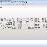
My job was to model and create drafts of 15 furnitures, based on drawings provided by the architect. The documentation was in Dutch with handwritten comments in English. The set contained custom made funritures, all for building in a school facility.
I always try to understand and get to know the whole project at the beginning. I do not start with one piece of furniture but with all of them. Solid by solid I analyze another drawings. Looking for common parts – maybe some future universal components. Write a list of materials used by the architect – which will later reduce the time needed to look for textures to create materials in Topsolid.
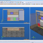
With consider construction of furniture, I am looking for accessories that I have not found in my resources. It’s best to look for ready-made solutions, so I helped myself with other websites:
This is the time when I as a engineer analyze the project, I make my comments, remarks on the customer’s drawings. I never start from modeling but from getting to know the project. It allows me to avoid huge corrects , errors in furniture parameterization, extend / speed up later modeling.
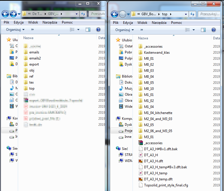
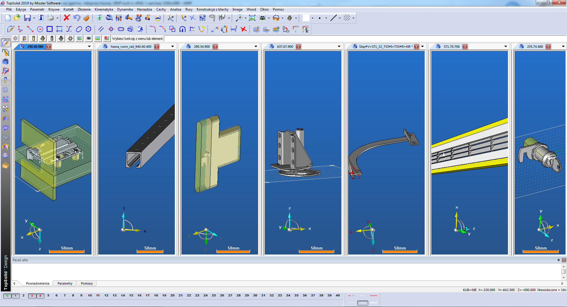
In the case of a new client, one of my first steps was to prepare Topsolid under this cooperation. I created separate CONFIG and GROUP folders to which I uploaded DRAFT file templates (from De Tender). That prepared configuration in Topsolid – we run with prepared shortcut to the program. Full path below:
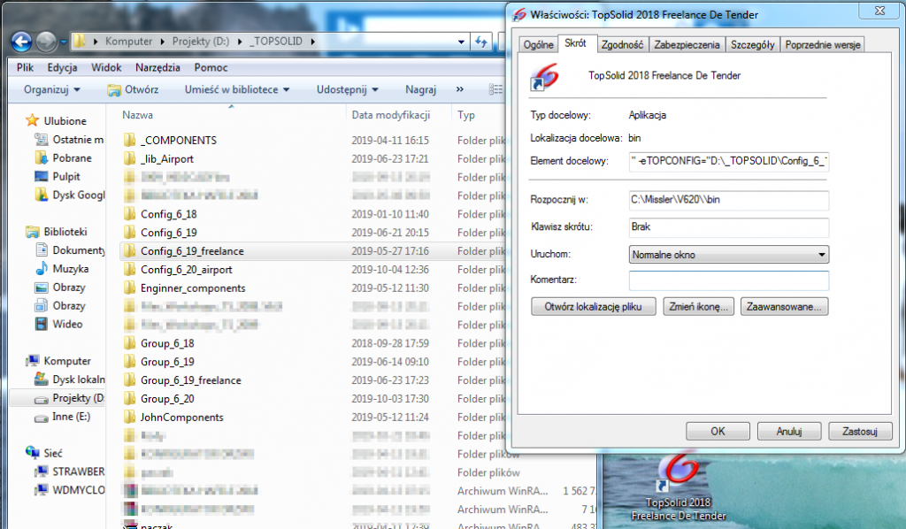
C:\Missler\V619\bin\top619.exe -eTOPGROUP=”D:\_TOPSOLID\Group_6_19_freelance” -eTOPCONFIG=”D:\_TOPSOLID\Config_6_19_freelance”
Preparation of disk space / network resource – for the proper directory structure and creating a universal top file template ( design document ) those are mine last steps before modeling. Here previous work pays off – I know the types of edge banding ,names of laminates – so I used them to create the appropriate codification for them.
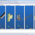
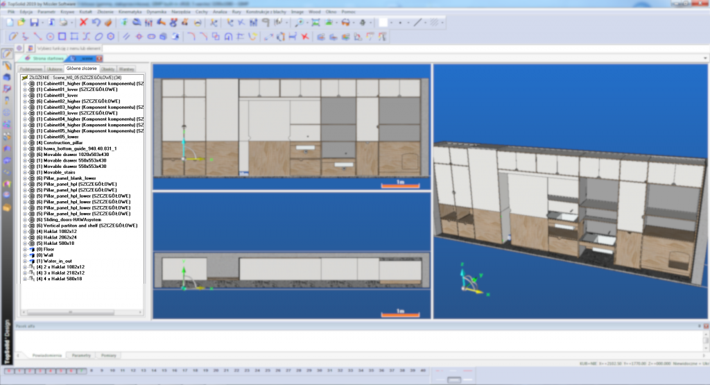
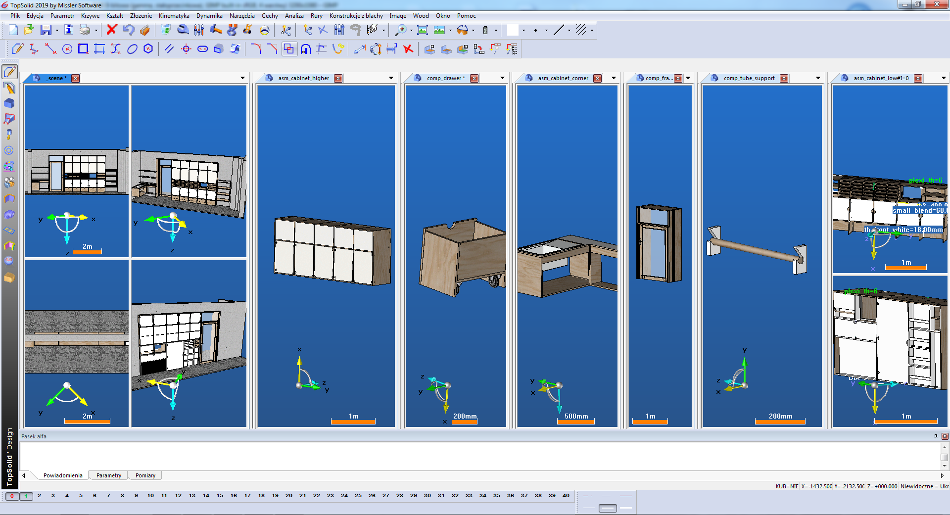
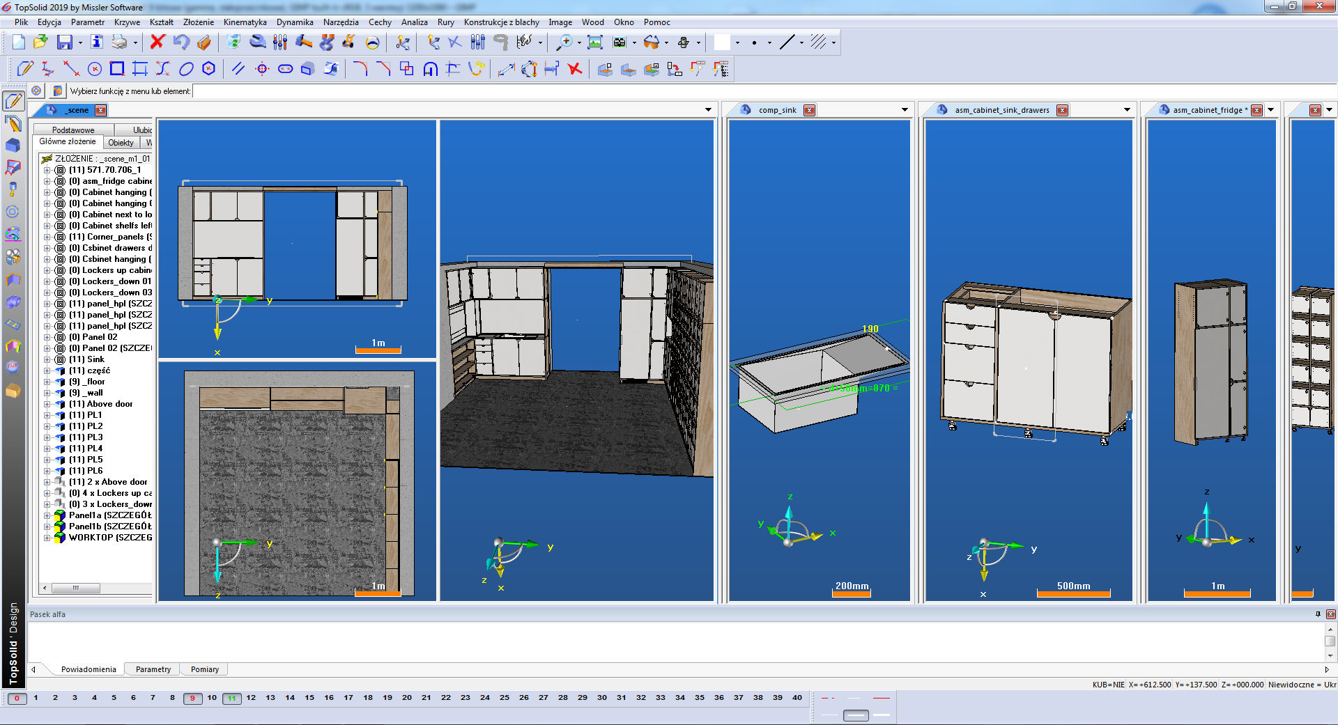
That prepared, I began modeling the first sub-assembly in Topsolid. Then the next ones, until the first assembly is closed.
The structure of the assembly itself is important for the draft. This is not about naming sub-assemblies – although this also matters to keep top file tree in order.
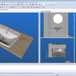
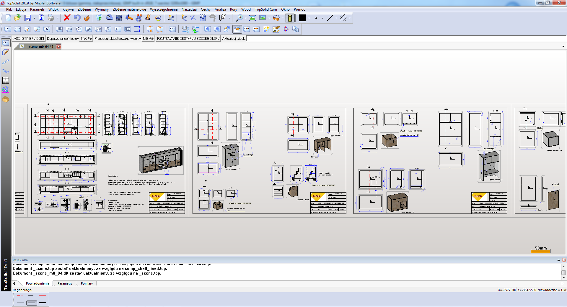
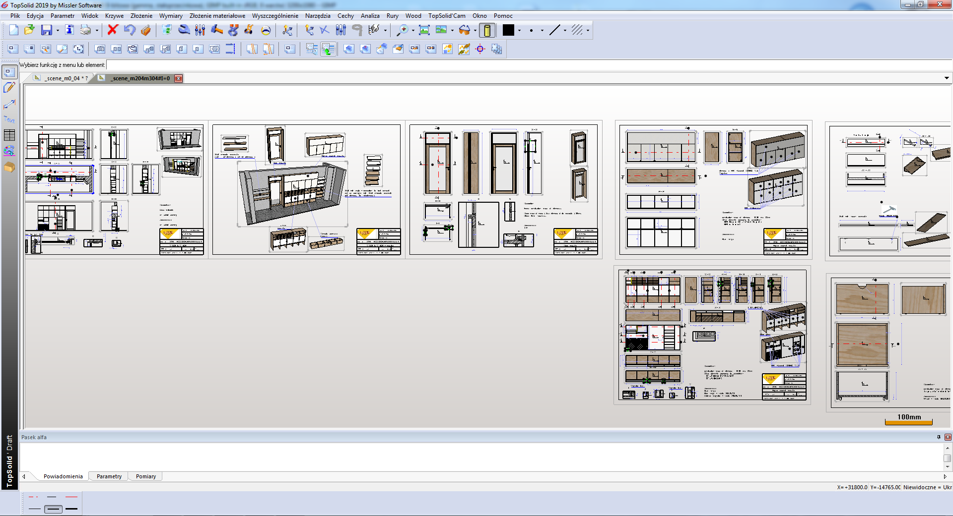
I often create drafts only after completing several furnitures. And if modeling goes smoothly, I continue with the next furniture. Drafts I leave at the end.
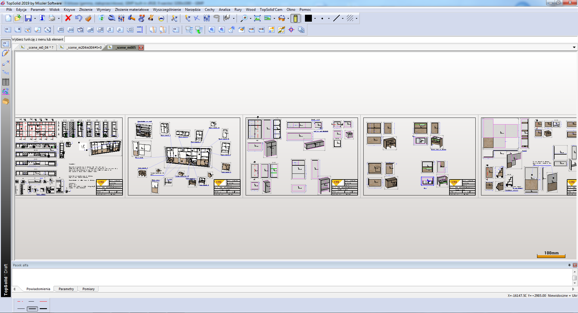
This has several advantages. Drafts will usually have similar descriptions, details and reference images. It is easier to move only between drafts. Often these are also copies of drafts with chagned reference to models. Flat documentation becomes more uniform. Performs the same actions: main view, auxiliary view, detail here, dimensioning, change of data in the drawing table etc.
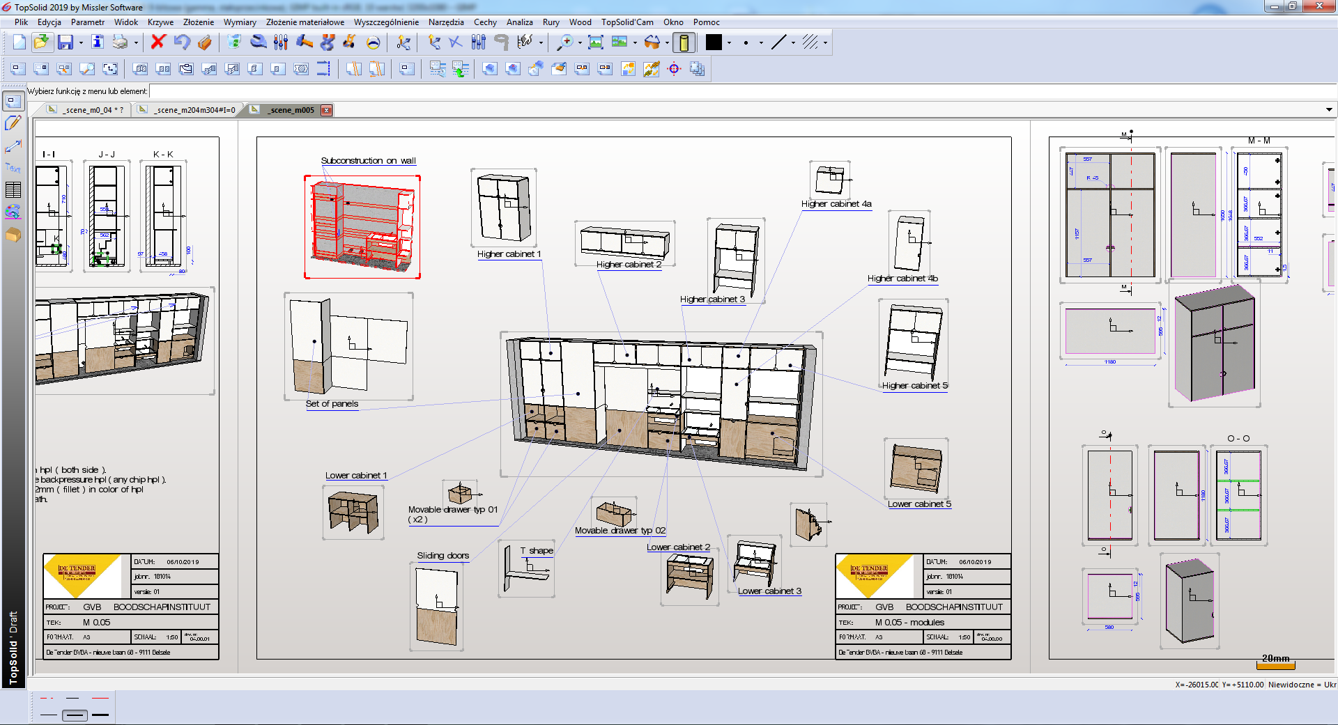
In one of the subpages, my draft shows the breakdown of the assembly into individual components – which allows production to better understand my idea. And it is easier to release it for cutting into a panel saw in sections.
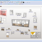
The person generating the BOM from subassemblies can use the properties – attributes of Topsolid to generate individual element names. Then production have no trouble with sorting the elements and assigning them to a given section of the furniture.
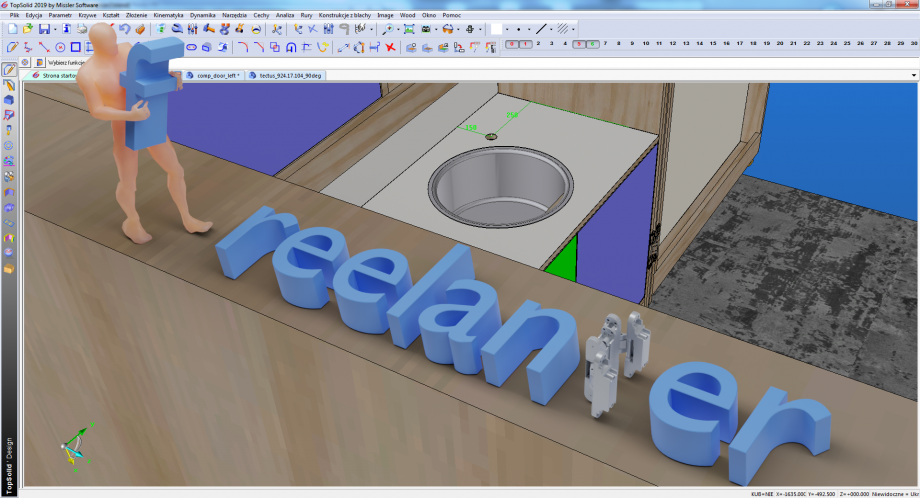
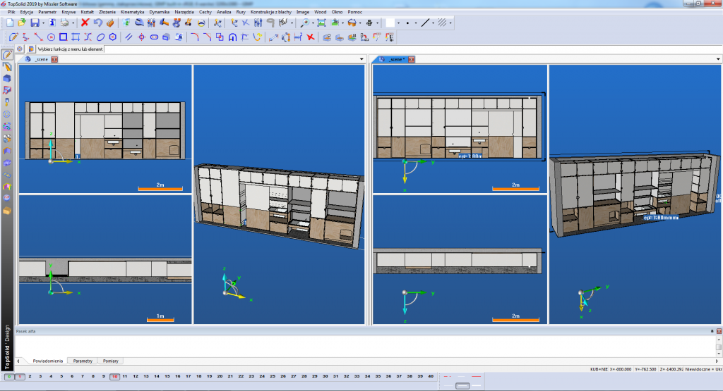
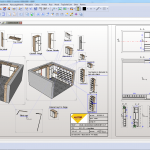
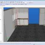
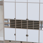
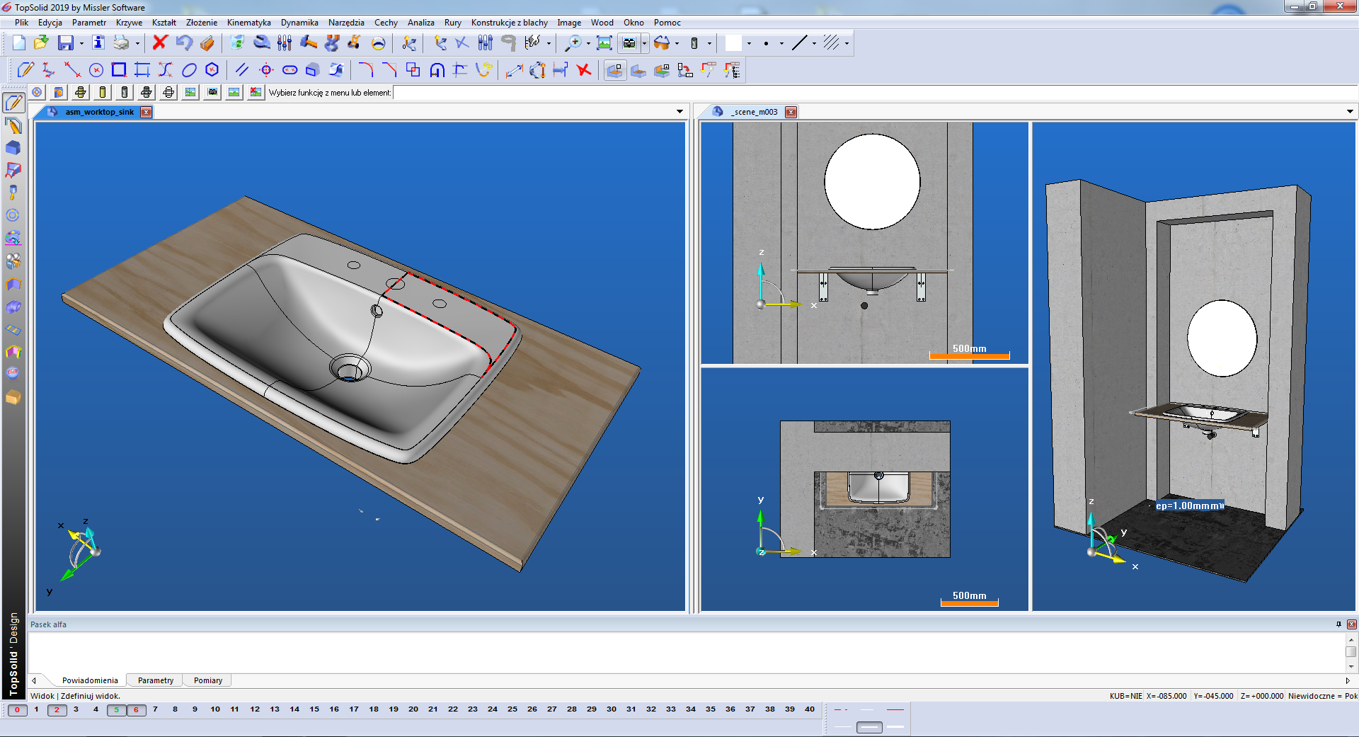
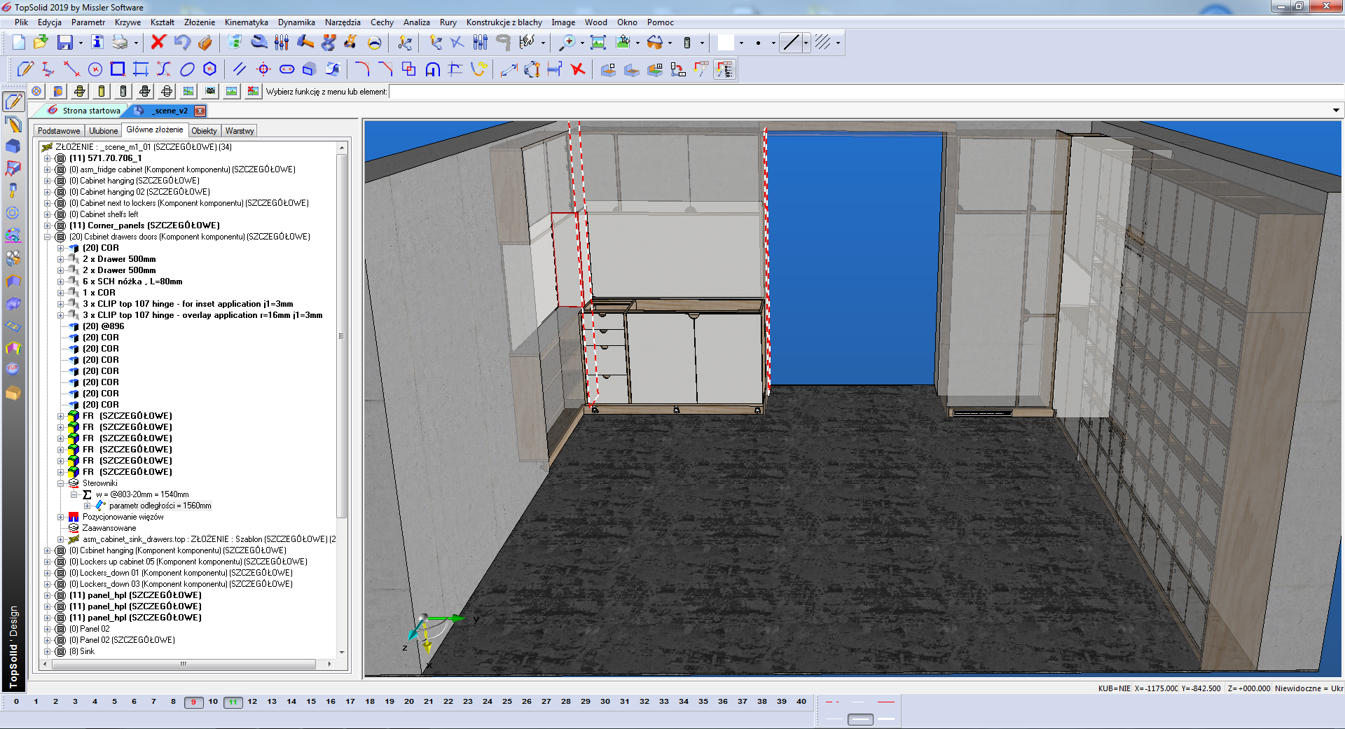
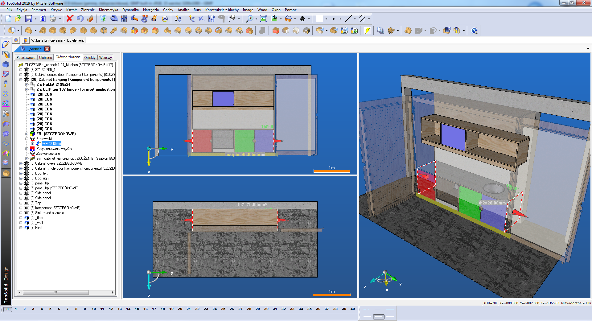
Creation of the furniture and its components was insufficient in many cases. So I model the scenes and the environment in which the furniture was assembled. This is where sub-assembly drivers lead the way. „Measurement from nature” – transfers the dimension to the model, where the furniture adapts the shape, number of elements, size to new parameters. Normal use of Topsolid 🙂
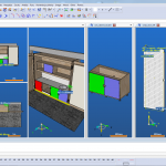
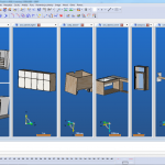
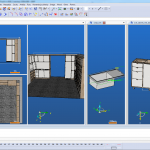
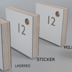
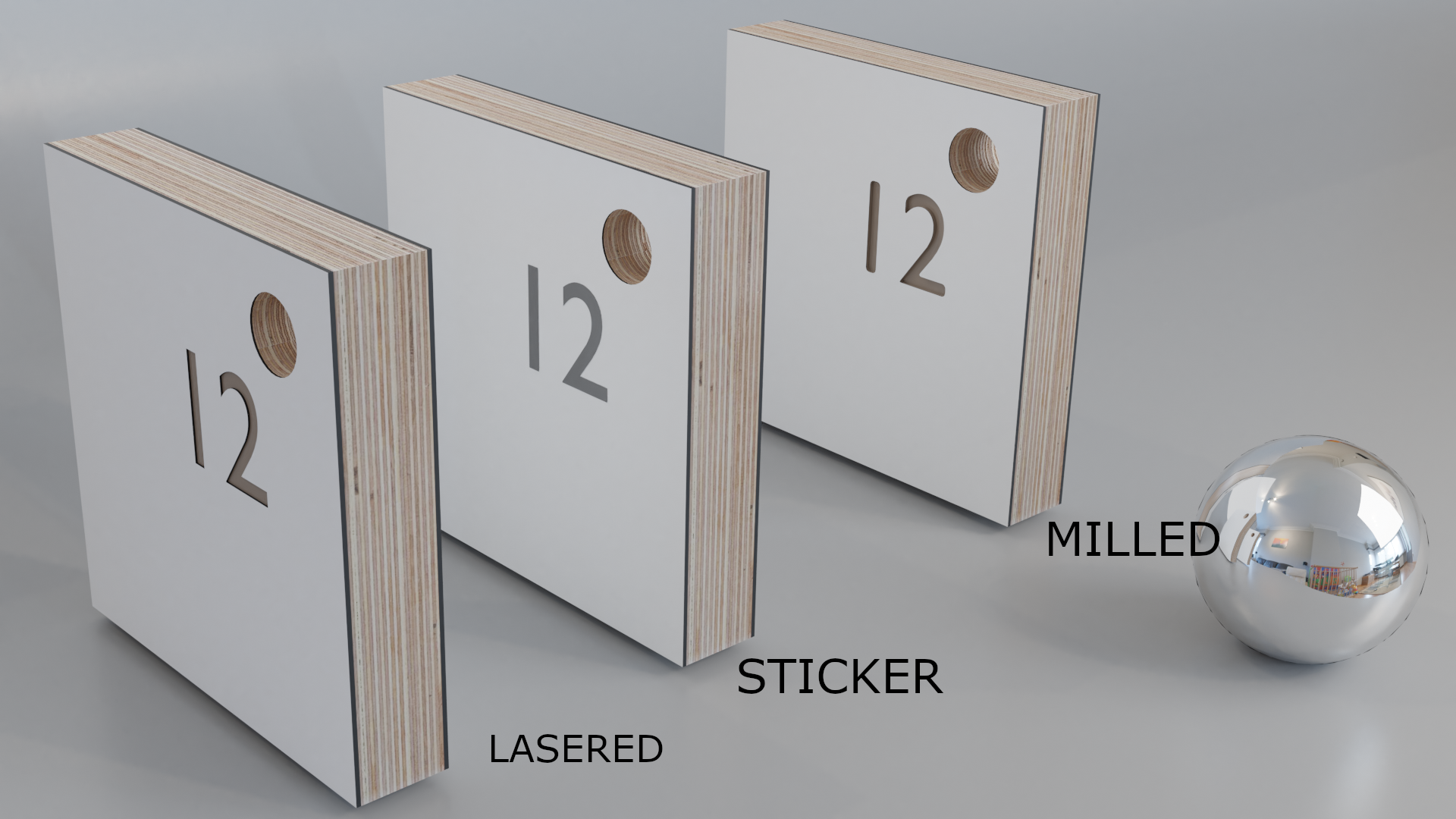
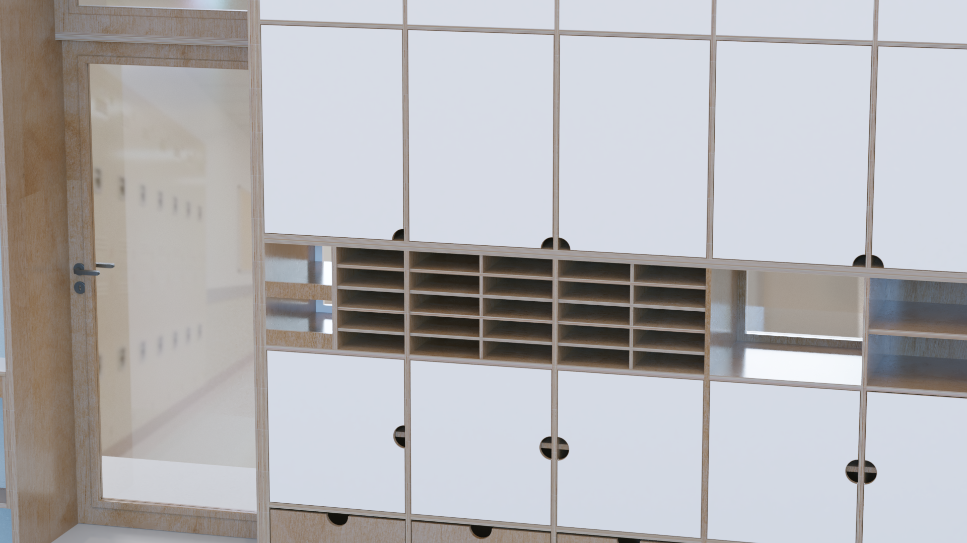
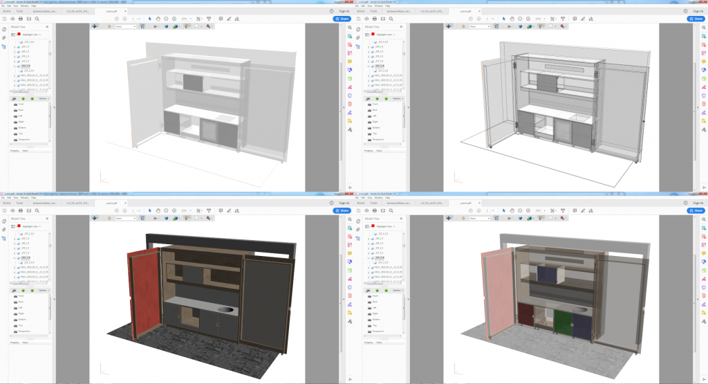
In addition, based on the models from Topsolid I create simple visualizations in Blender for easier comunication with the client. Topsolid exports files to several recognized CAD formats (including AutoCAD, Inventor) and mesh (STL, obj, vrlm etc.). Below, a few fast renderings (Blender 2.8), preparation of finishing elements (for the client’s decision), simple visualizations of the whole scene:

The drawing format in which we carried out the project with the client at the beginning were pdf-drafts. Here, every constructor has his own favourite pda exporter – BullZIP, PDFcreator, doPDF etc.
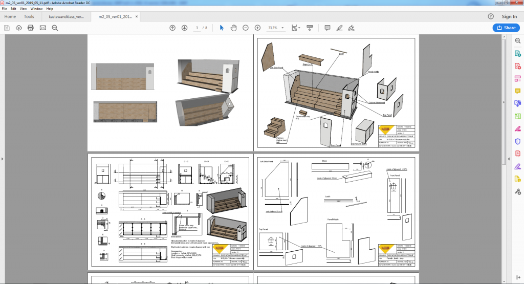
Topsolid allows you to save even 3D PDFs – they allow you to view the entire furniture and even turn off individual elements. The program that opens the PDF document must be Adobe Acrobat Reader.
Topsolid Viewer can be another method or form of dialogue. In link description [TOPSOLID VIWER ENG]
To transfer entire project from my Topsolid – after approval of draft / pdf – I used the export tool.
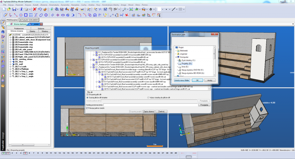
I usually pack this generated package of models, textures, data with the 7z program and send it by wetransfer.com. After downloading the data, the customer only has to import the project into their system with Topsolid.